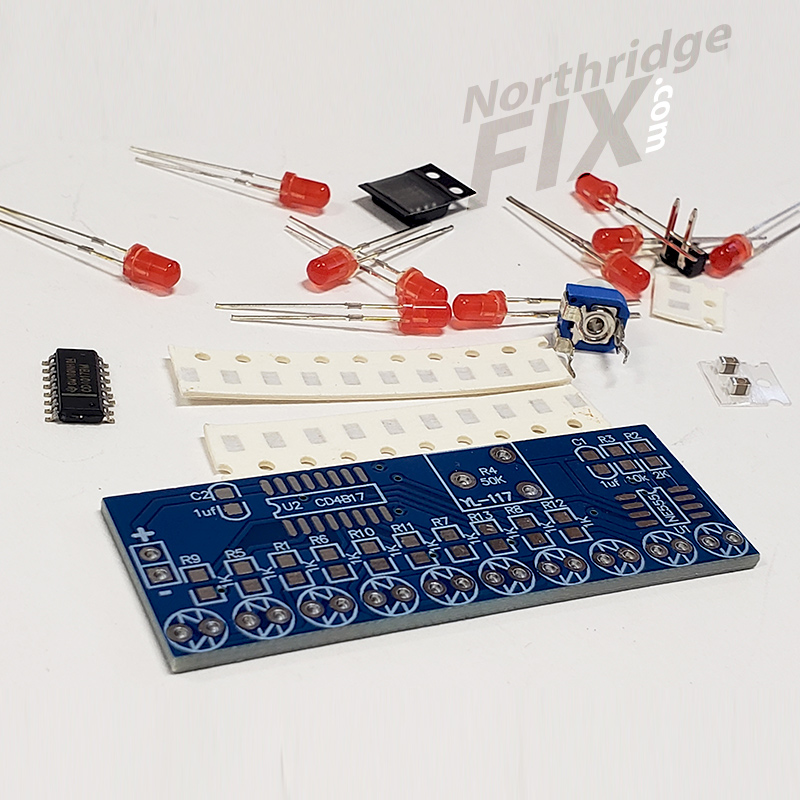
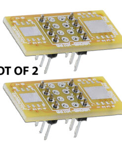
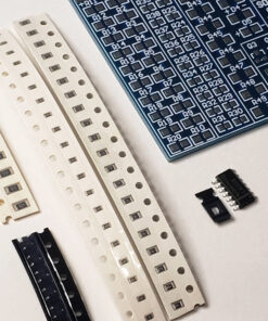
A great way to practice soldering. The DIY light chaser kit includes both SMD and through hole components. You get everything from resisters, capacitors, diodes, to LEDs and IC chips + more.
Factory Description – How does it work:
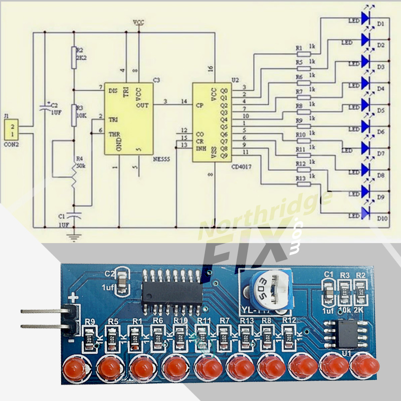
This Kit is a decimal counter circuit generated by the clock from the 555 multivibrator power through R2, R3, R4 charge the capacitor C1, C1 started when charging , NE555 2 feet still in low, so the output pin 3 goes high when power through R2, R3, R4 to charge C1 to 2/3 of the supply voltage , the output pin 3 level from high to low , NE555 conducting internal discharge , capacitor C1 through R4, R3, NE555 7 feet discharge until the voltage across C1 is less than 1 /3 of the supply voltage , NE555 and 3 feet level from low to high . C1 and charge again this cycle oscillations formed . Charging time : 0.695 (R2 + R3 + R4) C1, discharge time : 0.695 (R4 + R3) C1, R4 can be adjusted to control the output frequency of the oscillator , the oscillation clock signal is applied continuously NE555 CD4017 14 feet , the output terminal 10 is connected with the CD4017 10 LED, when the output terminal 10 turns CD4017 generated clock signal is applied at a high level , the D1 – D10 are sequentially lit to form a water -light effect .R4 adjusts LED flow rate.
Board size. 53mm x 19mm
Supply Voltage :2.5 – 14 .5 V

